Creo Sheet Metal Shell
Solid To Sheet Metal Conversion In Creo 2 0 Youtube

A Very Good Model To Practice Learn Drawing Reading And Model Creation 3d Modeling Tutorial Parametric Model

Creo 5 0 Absolute Beginners 3d Modeling Tutorial 3d Modeling Tutorial Tutorial Mechanical Design

Autodesk Inventor Tutorial For Beginners Exercise 8 Youtube Autodesk Inventor Autocad Isometric Drawing Inventor

Plastic Part Modeling Tutorial Design Tutorials Tutorial Parametric

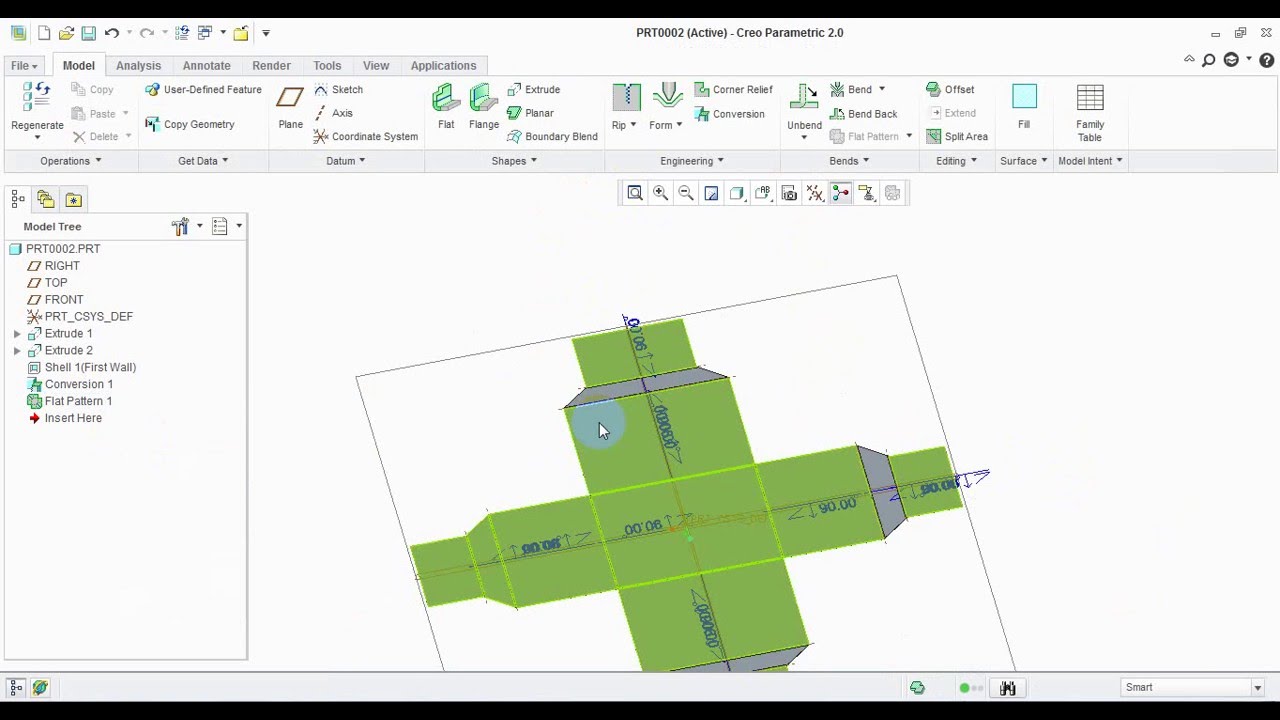
Tutorial Sheet Metal Conversion Two Examples Ptc Community

Choose the method best suited to the design task by using a variety of modeling methods including 2d 3d idealized shell or.
Creo sheet metal shell.

Sheetmetal Ptc Learning Connector

Creo Parametric Absolute Beginners Tutorials Mechanical Design Tutorial Parametric
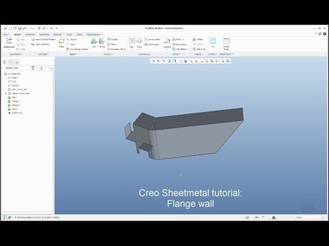
Creo Sheetmetal Tutorial How To Create Flange Wall Feature Youtube

Pin On Design
Source : pinterest.com
